
About this PNG to DXF tool
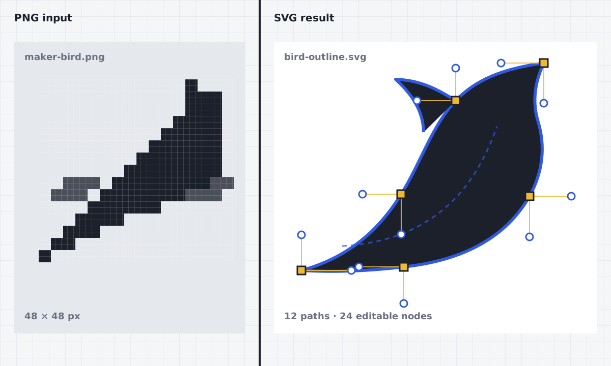
A PNG is a raster image made from pixels, while a DXF carries geometric entities used by many CAD and workshop applications. A useful PNG to DXF workflow therefore needs two stages: trace the visible artwork into vector paths, then translate those paths into exchange geometry. This tool keeps both stages in one browser workbench and shows the intermediate vector preview before any download.
The converter works best with logos, silhouettes, diagrams, and artwork that has clear boundaries. A transparent background can help, but transparency alone does not guarantee clean geometry. Anti-aliased edges, shadows, texture, and tiny marks may produce extra contours. Use the preset that matches the source, inspect the result, and remove details that are smaller than the real project needs. JPG and WebP files are accepted as a convenience, though PNG is the preferred input for this PNG to DXF page.
How it works
- 01
Upload the PNG
Choose a PNG with a distinct subject and enough resolution to show its edges. If possible, crop empty space and remove a noisy background before conversion. The image remains on your device.
- 02
Trace pixels into paths
Select a logo, silhouette, or photo preset and run the local VTracer pass. The tool converts groups of pixels into SVG curves that can be inspected before DXF export.
- 03
Clean the vector preview
Use the editor to correct or remove unwanted shapes. Review open-path warnings, thin islands, and duplicated-looking edges. Simpler geometry is generally easier to manage in CAD, CAM, or laser software.
- 04
Choose units and export DXF
Set millimeters or inches, review the machining options, and use the highlighted DXF button. SVG and PDF remain available when you need an editable master or a review copy.
Practical use cases
Logo outlines for shop software
Convert a flat, high-contrast brand mark or personal shop logo into geometry for a sign layout. Check the right to use any artwork you did not create, and expand or simplify tiny details before fabrication.
Silhouettes for laser projects
A black subject on a plain background can become a clear outer contour for ornaments, tags, or wall art. The PNG to DXF output still needs scale, cut operation, and machine settings assigned in the laser workflow.
Templates and reference profiles
Trace a photographed or scanned template into geometry that can be measured and refined in CAD. A photograph can introduce perspective distortion, so include a known dimension and correct the result in CAD when accuracy matters.
Simple craft and stencil shapes
Prepare bold shapes for stencil planning, paper craft, or cutting layouts. Look for enclosed islands and narrow bridges, and adapt them to the material and tool instead of assuming every traced detail will remain intact.
Browser-local tracing without an upload
The PNG is read by your browser and passed to the bundled tracing code on the same device. The local PNG to DXF workflow avoids sending the source artwork to a conversion server. Large or detailed images can take longer because the browser must analyze more color regions. Keep the tab open during processing and preserve the original image separately.
DXF geometry, units, and layers
A PNG to DXF result is an exchange file, not a complete manufacturing job. The unit choice helps establish intended scale, and color-based layers can help organize some artwork, but destination software may map layers and dimensions differently. Always open the file in the application you plan to use, confirm the imported measurement, close contours where required, and configure the actual tool or machine there.
PNG to DXF FAQ
- Can a PNG really become a DXF file?
- Yes, by tracing its pixel boundaries into vector paths first. The process is interpretive: it creates geometry that follows visible regions rather than recovering an original CAD drawing. Clean, high-contrast input usually produces the most manageable result.
- Why does my PNG to DXF result have double lines?
- A thick raster stroke has two visible edges, so tracing may create an outline around both sides instead of a single centerline. Use filled silhouettes when possible, simplify the SVG preview, or adjust the resulting geometry in CAD for centerline-specific work.
- Will transparent PNG backgrounds be ignored?
- Transparent space usually helps separate the subject, but semi-transparent edge pixels and shadows may still create regions. Inspect the preview and remove unwanted contours before export rather than relying on transparency as an automatic cleanup step.
- Is the exported file ready for laser or CNC use?
- It is geometry for compatible software, not machine code or a safety-checked job. Verify size, closed paths, duplicate contours, operation order, kerf or tool offsets, feeds, speeds, material, hold-down, and every machine-specific setting before running equipment.